| General information |
| Product type designation |
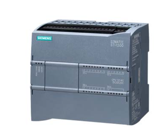
CPU 1214C DC/DC/DC |
| Engineering with |
| ● Programming package |
STEP 7 V10.5 or higher |
| Supply voltage |
| Rated value (DC) |
|
| ● 24 V DC |
Yes |
| permissible range, lower limit (DC) |
20.4 V |
| permissible range, upper limit (DC) |
28.8 V |
| Load voltage L+ |
| ● Rated value (DC) |
24 V |
| ● permissible range, lower limit (DC) |
20.4 V |
| ● permissible range, upper limit (DC) |
28.8 V |
| Input current |
| Current consumption, max. |
1.5 A; 24 V DC |
| Inrush current, max. |
12 A; at 28.8 V DC |
| Output current |
| for backplane bus (5 V DC), max. |
1 600 mA; Max. 5 V DC for SM and CM |
| Encoder supply |
| 24 V encoder supply |
| ● 24 V |
Permissible range: 20.4V to 28.8V |
| Power loss |
| Power loss, typ. |
12 W |
| Memory |
| Work memory |
| ● integrated |
50 kbyte |
| Load memory |
| ● integrated |
2 Mbyte |
| ● Plug-in (SIMATIC Memory Card), max. |
24 Mbyte; with SIMATIC memory card |
| Backup |
| ● present |
Yes; Entire project maintenance-free in the integral EEPROM |
| ● without battery |
Yes |
| CPU processing times |
| for bit operations, typ. |
0.1 µs; / Operation |
| for word operations, typ. |
12 µs; / Operation |
| for floating point arithmetic, typ. |
18 µs; / Operation |
| CPU-blocks |
| Number of blocks (total) |
DBs, FCs, FBs, counters and timers. The maximum number of addressable blocks ranges from 1 to 65535. There is no restriction, the entire working memory can be used |
| OB |
| ● Number, max. |
Limited only by RAM for code |
| Data areas and their retentivity |
| Retentive data area (incl. timers, counters, flags), max. |
2 048 byte |
| Flag |
| ● Size, max. |
8 kbyte; Size of bit memory address area |
| Address area |
| I/O address area |
| ● Inputs |
1 024 byte |
| ● Outputs |
1 024 byte |
| Process image |
| ● Inputs, adjustable |
1 kbyte |
| ● Outputs, adjustable |
1 kbyte |
| Hardware configuration |
| Number of modules per system, max. |
3 comm. modules, 1 signal board, 8 signal modules |
| Time of day |
| Clock |
| ● Hardware clock (real-time) |
Yes |
| ● Backup time |
240 h; Typical |
| ● Deviation per day, max. |
±60 s/month at 25 °C |
| Digital inputs |
| Number of digital inputs |
14; Integrated |
| ● of which inputs usable for technological functions |
6; HSC (High Speed Counting) |
| Source/sink input |
Yes |
| Input voltage |
| ● Rated value (DC) |
24 V |
| ● for signal “0” |
5 V DC at 1 mA |
| ● for signal “1” |
15 V DC at 2.5 mA |
| Input current |
| ● for signal “1”, typ. |
1 mA |
| Input delay (for rated value of input voltage) |
| for standard inputs |
| — parameterizable |
0.2 ms, 0.4 ms, 0.8 ms, 1.6 ms, 3.2 ms, 6.4 ms and 12.8 ms, selectable in groups of four |
| — at “0” to “1”, min. |
0.2 ms |
| — at “0” to “1”, max. |
12.8 ms |
| for interrupt inputs |
| — parameterizable |
Yes |
| for technological functions |
| — parameterizable |
Single phase: 3 at 100 kHz & 1 at 30 kHz, differential: 3 at 80 kHz & 1 at 30 kHz |
| Cable length |
| ● shielded, max. |
500 m; 50 m for technological functions |
| ● unshielded, max. |
300 m; for technological functions: No |
| Digital outputs |
| Number of digital outputs |
10 |
| ● of which high-speed outputs |
2; 100 kHz Pulse Train Output |
| Short-circuit protection |
No; to be provided externally |
| Limitation of inductive shutdown voltage to |
L+ (-48 V) |
| Switching capacity of the outputs |
| ● with resistive load, max. |
0.5 A |
| ● on lamp load, max. |
5 W |
| Output voltage |
| ● for signal “1”, min. |
20 V |
| Output current |
| ● for signal “1” rated value |
0.5 A |
| ● for signal “0” residual current, max. |
0.1 mA |
| Output delay with resistive load |
| ● “0” to “1”, max. |
1 µs |
| ● “1” to “0”, max. |
5 µs |
| Switching frequency |
| ● of the pulse outputs, with resistive load, max. |
100 kHz |
| Relay outputs |
| ● Number of relay outputs |
10 |
| Cable length |
| ● shielded, max. |
500 m |
| ● unshielded, max. |
150 m |
| Analog inputs |
| Number of analog inputs |
2 |
| Input ranges |
| ● Voltage |
Yes |
| Input ranges (rated values), voltages |
| ● 0 to +10 V |
Yes |
| — Input resistance (0 to 10 V) |
≥100k ohms |
| Cable length |
| ● shielded, max. |
100 m; twisted and shielded |
| Analog outputs |
| Number of analog outputs |
0 |
| Cable length |
| ● shielded, max. |
100 m; shielded, twisted pair |
| Analog value generation for the inputs |
| Integration and conversion time/resolution per channel |
| ● Resolution with overrange (bit including sign), max. |
10 bit |
| ● Integration time, parameterizable |
Yes |
| ● Conversion time (per channel) |
625 µs |
| Encoder |
| Connectable encoders |
| ● 2-wire sensor |
Yes |
| 1. Interface |
| Interface type |
PROFINET |
| Isolated |
Yes |
| automatic detection of transmission rate |
Yes |
| Autonegotiation |
Yes |
| Autocrossing |
Yes |
| Interface types |
| ● RJ 45 (Ethernet) |
Yes |
| Protocols |
| ● PROFINET IO Controller |
Yes |
| Protocols |
| Supports protocol for PROFINET IO |
Yes |
| PROFIsafe |
No |
| PROFIBUS |
No |
| AS-Interface |
No |
| Protocols (Ethernet) |
| ● TCP/IP |
Yes |
| Open IE communication |
| ● TCP/IP |
Yes |
| ● ISO-on-TCP (RFC1006) |
Yes |
| Web server |
| ● supported |
Yes |
| ● User-defined websites |
Yes |
| Further protocols |
| ● MODBUS |
No |
| communication functions / header |
| S7 communication |
| ● supported |
Yes |
| ● as server |
Yes |
| Number of connections |
| ● overall |
15; dynamically |
| Test commissioning functions |
| Status/control |
| ● Status/control variable |
Yes |
| ● Variables |
Inputs/outputs, memory bits, DBs, distributed I/Os, timers, counters |
| Forcing |
| ● Forcing |
Yes |
| Integrated Functions |
| Counter |
|
| ● Number of counters |
6 |
| ● Counting frequency, max. |
100 kHz |
| Frequency measurement |
Yes |
| controlled positioning |
Yes |
| PID controller |
Yes |
| Number of alarm inputs |
4 |
| Number of pulse outputs |
2 |
| Limit frequency (pulse) |
100 kHz |
| Potential separation |
| Potential separation digital inputs |
| ● Potential separation digital inputs |
No |
| ● between the channels, in groups of |
1 |
| Potential separation digital outputs |
| ● Potential separation digital outputs |
Yes |
| ● between the channels |
No |
| ● between the channels, in groups of |
2 |
| Permissible potential difference |
| between different circuits |
500 V DC between 24 V DC and 5 V DC |
| EMC |
| Interference immunity against discharge of static electricity |
| ● Interference immunity against discharge of static electricity acc. to IEC 61000-4-2 |
Yes |
| — Test voltage at air discharge |
8 kV |
| — Test voltage at contact discharge |
6 kV |
| Interference immunity to cable-borne interference |
| ● Interference immunity on supply lines acc. to IEC 61000-4-4 |
Yes |
| ● Interference immunity on signal cables acc. to IEC 61000-4-4 |
Yes |
| Interference immunity against voltage surge |
| ● Interference immunity on supply lines acc. to IEC 61000-4-5 |
Yes |
| Interference immunity against conducted variable disturbance induced by high-frequency fields |
| ● Interference immunity against high-frequency radiation acc. to IEC 61000-4-6 |
Yes |
| Emission of radio interference acc. to EN 55 011 |
| ● Limit class A, for use in industrial areas |
Yes; Group 1 |
| ● Limit class B, for use in residential areas |
Yes; When appropriate measures are used to ensure compliance with the limits for Class B according to EN 55011 |
| Degree and class of protection |
| IP degree of protection |
IP20 |
| Standards, approvals, certificates |
| CE mark |
Yes |
| cULus |
Yes |
| FM approval |
Yes |
| RCM (formerly C-TICK) |
Yes |
| Ambient conditions |
| Free fall |
| ● Fall height, max. |
0.3 m; five times, in product package |
| Ambient temperature during operation |
| ● min. |
0 °C |
| ● max. |
55 °C |
| ● horizontal installation, min. |
0 °C |
| ● horizontal installation, max. |
55 °C |
| ● vertical installation, min. |
0 °C |
| ● vertical installation, max. |
45 °C |
| ● permissible temperature change |
5°C to 55°C, 3°C / minute |
| Ambient temperature during storage/transportation |
| ● min. |
-40 °C |
| ● max. |
70 °C |
| Air pressure acc. to IEC 60068-2-13 |
| ● Operation, min. |
795 hPa |
| ● Operation, max. |
1 080 hPa |
| ● Storage/transport, min. |
660 hPa |
| ● Storage/transport, max. |
1 080 hPa |
| Altitude during operation relating to sea level |
| ● Installation altitude, min. |
-1 000 m |
| ● Installation altitude, max. |
2 000 m |
| Relative humidity |
| ● Operation, max. |
95 %; no condensation |
| Vibrations |
| ● Vibration resistance during operation acc. to IEC 60068-2-6 |
2 g (m/s²) wall mounting, 1 g (m/s²) DIN rail |
| ● Operation, tested according to IEC 60068-2-6 |
Yes |
| Shock testing |
| ● tested according to IEC 60068-2-27 |
Yes; IEC 68, Part 2-27 half-sine: strength of the shock 15 g (peak value), duration 11 ms |
| Pollutant concentrations |
| ● SO2 at RH < 60% without condensation |
S02: < 0.5 ppm; H2S: < 0.1 ppm; RH < 60% condensation-free |
| configuration / header |
| configuration / programming / header |
| Programming language |
| — LAD |
Yes |
| — FBD |
Yes |
| — SCL |
Yes |
| programming / cycle time monitoring / header |
| ● adjustable |
Yes |
| Dimensions |
| Width |
110 mm |
| Height |
100 mm |
| Depth |
75 mm |
Reviews
There are no reviews yet.